5. Operation
The Bridge12 MPS can be completely operated from the front panel. To the right of the TFT display are three silver push buttons and a dial (rotary encoder) that can be rotated in either direction. The top two buttons are used to either select and change the frequency, or select and change the power level (see Figure 5.1).
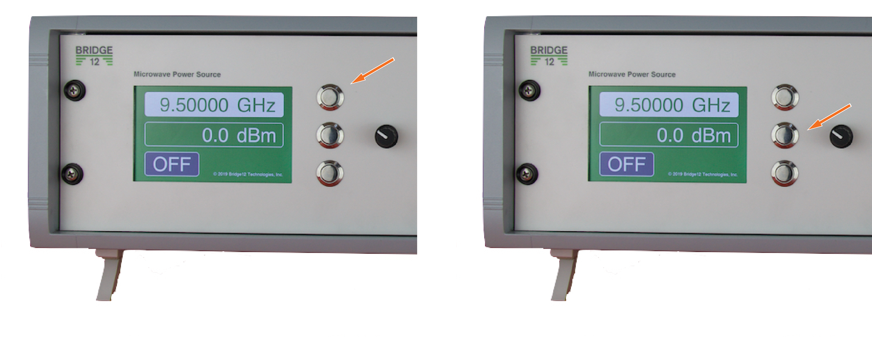
Figure 5.1 Left: MPS set to change the output frequency. Right: MPS set to change the output power level
5.1. Manual Operation
5.1.1. Setting the Output Frequency
To set the microwave output frequency:
Push the top button located to the right of the screen. The background color of the frequency will change from green to white (see Figure 5.1, left).
Using the rotary encoder, dial in the desired output frequency. Turn the dial clockwise to increase the frequency and counter clockwise to decrease the frequency. The step size to increase or decrease the frequency will change depending on how fast the dial is turned. For large steps, quickly turn the dial. For fine adjustments, turn the dial one click at a time.
5.1.2. Setting the Output Power
To set the microwave output power:
Push the middle button located to the right of the screen. The background color of the amplitude will change from green to white (see Figure 5.1, right).
Using the rotary encoder, dial in the desired output power. Turn the dial clockwise to increase the output power level and counter clockwise to decrease the output power level. The step size to increase or decrease the power level will change depending on how fast the dial is turned. For large steps, quickly turn the dial. For fine adjustments, turn the dial one click at a time.
Note
The power on the MPS system is given in dBm to easily facilitate displaying power levels over several orders of magnitude. This unit may be foreign to some researchers and a conversion table is given in the appendix to convert the power reading into Watts (see Table 9.1).
5.1.3. Switching between EPR and DNP Operation
Warning
Do not enable the microwave power without a load (e.g. tuned EPR cavity) attached to the output. When no load is connected, the output power is reflected into the system and can lead to permanent damages.
The Bridge12 MPS can control an external waveguide switch. The waveguide switch is part of the optional Bridge12 ODNP Connection Kit and is installed between the EPR bridge and the EPR resonator to easily switch between EPR and DNP operation. For details about the Connection Kit and how to install it, please consult the Connection Kit manual.
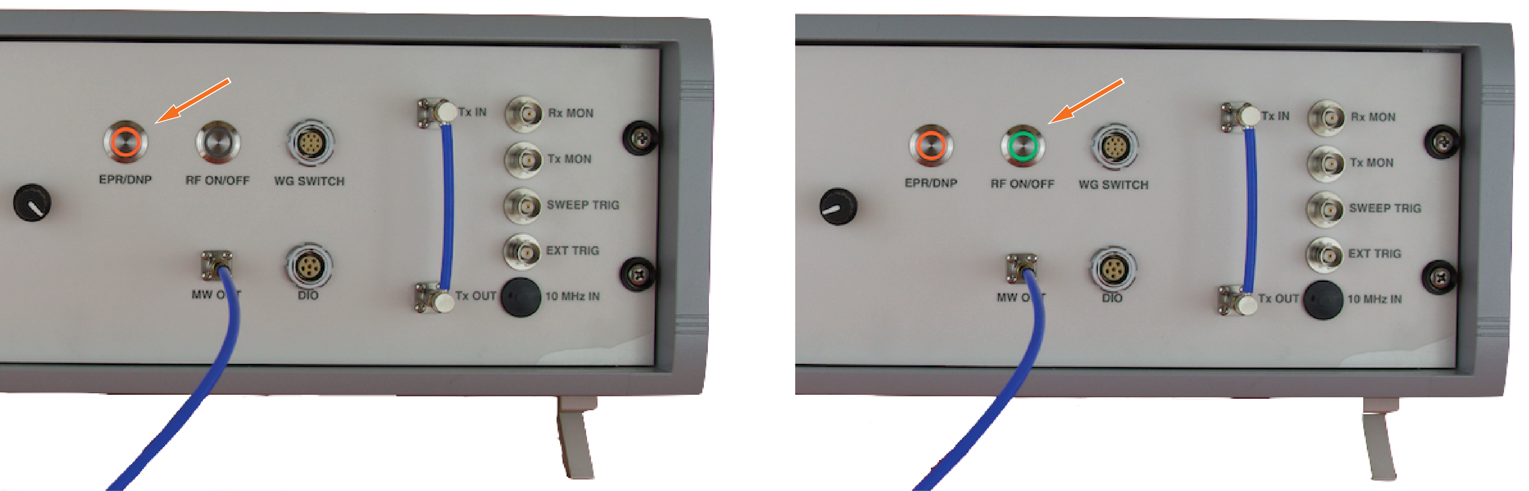
Figure 5.2 Left: Waveguide switch control button (orange). Right: Microwave (RF) ON/OFF button (green)
To switch to DNP operation, simply press the button labeled EPR/DNP. If your system is equipped with a waveguide switch, you will hear the waveguide switch changing direction. In any case, the orange light of the button will light up to indicate that the system is switched into DNP operation mode (see Figure 5.2). A schematic explaining the function of the waveguide switch is shown below.
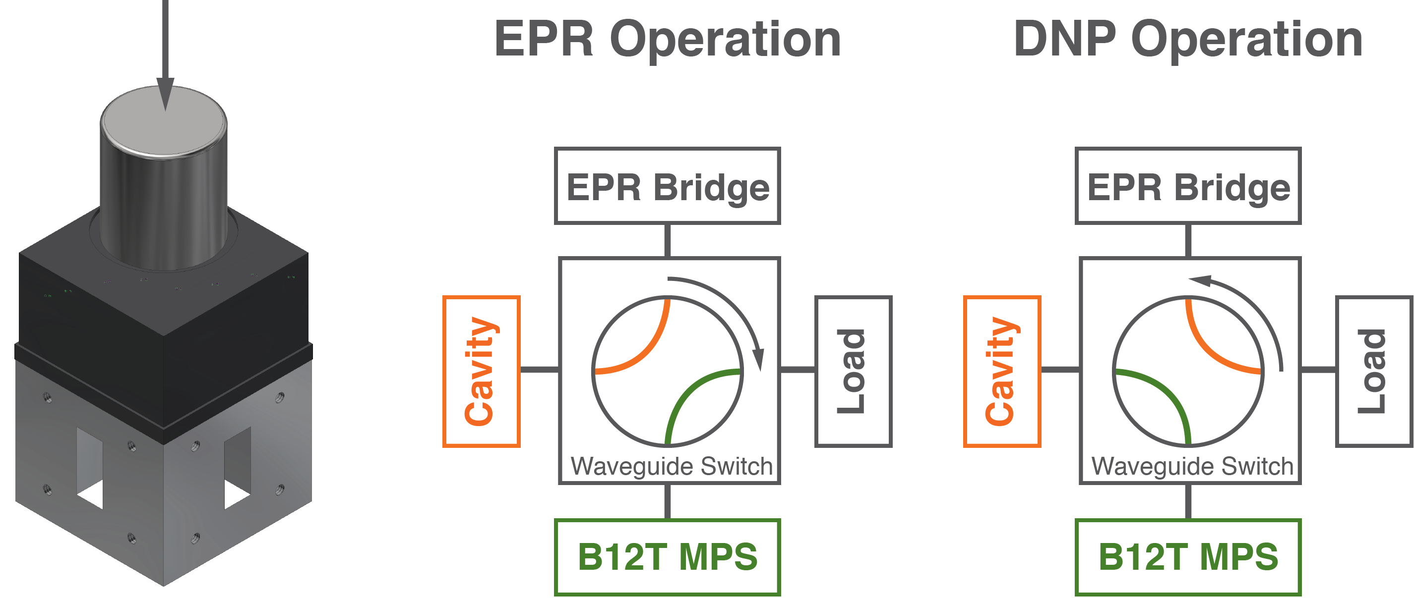
Figure 5.3 Waveguide switch positions
The waveguide switch has four ports. The way the ports are connected depends upon the position of the waveguide switch (see Figure 12, middle and right). The position of the switch is indicated on the top of the silver cap (see Figure 12 left).
Note
For safety reason, the microwave power will always be disabled when the waveguide switch is switched from DNP operation to EPR. Switching back to the DNP mode will not automatically enable the microwave power.
The microwave power can only be enabled if the waveguide switch is in the DNP position (orange button light is on). Even if your system is not equipped with a waveguide switch, the EPR/DNP button must be pressed before the microwave power can be enabled. This feature can be disabled upon special request in the firmware.
5.1.4. Enabling/Disabling the Output Power
By default, the output power is disabled when the Bridge12 MPS is initially powered up. To enable the microwave output power, make sure the system is in DNP mode (orange light is on) and press the button labeled RF ON/OFF. The button will light up with a green light and the status on the display will change from OFF to ON (see Figure 5.2). Pressing the same button again will disable the microwave output power.
5.1.5. Using the External Trigger
The output power of the Bridge12 MPS can be controlled (modulated) using an external trigger connected to the front panel BNC connector labeled “EXT TRIG”. This is an optional feature. Please make sure this feature is requested at the time of ordering the MPS. Please contact Bridge12 at info@bridge12.com with any questions regarding this feature.
The external trigger accepts a TTL signal (low: < 0.8 V, high: > 2 V). Please make sure to not exceed these limits. To enable the external trigger:
Press and hold the microwave ON/OFF button for at least 3 seconds.
The background of the output power indicator on the Main Screen will change to EXT (with an orange background color).
The unit is now ready to be controlled by an external trigger. To return to manual mode, press the microwave ON/OFF button again.
5.2. Tuning the EPR Resonator
5.2.1. Coarse Tuning
To tune the resonator first switch to the Sweep Screen (see Figure 2.4). If this is the first time that the sweep screen is entered, no sweep data is available and only a flat line at the bottom of the sweep screen is displayed. To perform a cavity sweep:
Set the center frequency (an initial estimate is sufficient). Press the frequency button (top button of the three buttons to the right of the display) and dial the frequency using the front panel dial.
Use the default sweep width of 250 MHz for the first sweep.
Switch the system into DNP mode.
Enable the RF output.
Press the sweep button (third button of the three buttons to the right of the display) to perform a sweep. The system will perform sweeps of the microwave frequency.
Press the frequency button and adjust the frequency so that the cavity dip is aligned with the center vertical line of the display. Adjust the iris coupling to match the resonator.
Once you found the resonator dip you can decrease the sweep width by pressing the center button of the three buttons to the right of the display. By pressing this button you will cycle through different predefined sweep widths: 250, 100, 50 and 10 MHz.
Once you followed these steps, you will have a fairly matched and tuned microwave resonator and you can move on to fine tune the resonator is described in the next section.
5.2.2. Fine Tuning
For fine tuning of the resonator switch to the Operate Screen (see Figure 2.5). Fine tuning is important before starting an ODNP experiment when using high microwave power levels to ensure the resonator is critically coupled. For this process the reflected microwave power is monitored:
With the microwave output power disabled, dial in the resonance frequency of the empty resonator (see the previous section to determine the center frequency).
Switch the microwave power ON and slowly increase the microwave output power to about 10 dBm. The exact value is not critical, but should not exceed 20 dBm.
Slowly vary the microwave output frequency and monitor the reflected power. At a certain frequency, a clear power minimum should be detected if the resonator is critically coupled.
Set the microwave frequency to a value corresponding to the minimum reflected power. This is the resonance frequency of the EPR resonator.
Check that the resonator is critically coupled. Slowly (!) turn the iris screw of the resonator and observe the reflected microwave power. Ensure that the reflected power is at a minimum.
Slowly increase or decrease the microwave frequency. Adjust if necessary to minimize the reflected microwave power.
Increase the microwave output power and repeat steps 5 through 7.
If the microwave resonator is critically coupled, the reflected microwave power will not increase when the forward power is increased. At high output power levels (> 30 dBm, 1 W) the reflected output power may change, but can corrected by moving the microwave frequency. This is due to heating effects inside the EPR resonator, which will lead to thermal expansion of the cavity and the resonance frequency will decrease slightly.
Note
During experiments, make sure of a constant flow of air through the resonator. This helps compensate for microwave induced sample heating effects.
5.3. Enabling the Frequency Lock
The Bridge12 MPS can operate in a Frequency Lock mode which constantly minimizes the reflected power from the microwave bridge by varying the microwave frequency. This mode is only available on the Operate Screen while the microwave output is enabled. The lock mode will be automatically turned off upon exiting the operate view or disabling the microwave output.
The lock feature can be enabled/disabled by pressing the 3rd (bottom silver) button next to the display. When the lock feature is enabled, the text color indicating the frequency will change to orange and the word “LOCK” will be displayed.
If the microwave frequency is within a few MHz of the resonator frequency, the lock feature should automatically find the center of the dip. If the microwave frequency is not close to the resonator frequency, it is unlikely the lock feature will be able to find the dip. The lock feature can aid in fine tuning the microwave resonator. A brief description of tuning with the lock feature is given below:
Set the microwave power to 10 dBm and set the microwave frequency to within a few MHz of the resonator frequency.
Make sure the operate view is displayed and enable the microwave output.
Enable lock mode by pressing the 3rd button next to the display. Once enabled, the frequency should change to minimize the reflections from the resonator. This may take a moment until the frequency is centered on the dip.
Once the Rx monitor has stabilized to a minimum value, slowly adjust the iris screw to minimize the reflections from the resonator (Rx).
The resonator is critically coupled when the Rx monitor reading is minimized.
If required, steps 4 and 5 can be repeated at higher power.
At high microwave power, e.g. > 30 dBm, the microwaves will induce significant heating in the cavity walls which will reduce the resonance frequency of the resonator. At very high powers, e.g. 40 dBm, the frequency can shift by more than 5 MHz. The lock feature is intended to compensate for temperature dependent shifts in the frequency of the resonator. Several of the default lock parameters are accessible through the serial port. These are detailed in the remote interface section.
5.4. Status Screen
5.4.1. Microwave Amplifier Temperature Monitor
The Bridge12 MPS continuously monitors the temperature of the microwave amplifier and disables the output power if the amplifier temperature reaches 55ºC. The amplifier temperature is displayed on the Status Screen.
If the MPS frequently overheats and the microwave power is disabled, contact Bridge12 immediately at support@bridge12.com.