2. Overview
This section of the manual will give a general overview of the system and its capabilities. For specific instructions how to operate the instrument please consult the Operation section of the manual. The system has several different screens that can be accessed by pressing the rotary encoder on the front panel. The screens are in the following order:
The Status Screen is an additional screen, which is accessible by pressing and holding the rotary encoder button for > 2 seconds.
2.1. System screens
2.1.1. Main Screen
Once the Bridge12 MPS has started and completed its initialization the system shows the main screen (see Figure 2.1). The system is ready.

Figure 2.1 MPS Main Screen with RF output power OFF.
To enable RF power output, switch the MPS to DNP and press the RF ON/OFF button. When the EPR/DNP button is pressed and the system switches to DNP mode the orange light of the button comes on. When the RF ON/OFF button is pressed and the RF power is enabled the green light of the button comes on. Also, on the main screen, the grey background changes to red, indicating that the output power is enabled (see Figure 2.2).

Figure 2.2 MPS Main Screen with RF output power ON.
Warning
Do not enable the microwave power without a load (e.g. tuned EPR cavity) attached to the output. When no load is connected, the output power is reflected into the system and can lead to permanent damages.
If you like to use an external trigger you can switch the MPS into a mode that accepts an external TTL trigger using the BNC connector located on the front panel. This mode is indicated by the orange background (see Figure 2.3).

Figure 2.3 MPS Main Screen with RF output power in external trigger mode.
The RF status (ON/OFF/EXT) can also be controlled through the serial interface. For more information about how to use the remote interface see section Remote Interface .
2.1.2. Sweep Screen
The sweep screen allows measuring the reflected power from the microwave cavity. Using this screen it is possible to perform a critical tuning of the resonator.

Figure 2.4 MPS Sweep Screen (the actual screen may differ depending on the installed firmware version)
A typical screen is shown in Figure 2.4. The top row indicates the center frequency (CF) of the sweep. In this case it is set to 9.5 GHz. The default microwave power to perform a sweep is set to 10 dBm. Other values can be set through the serial interface. If the RF sweep power is not equal to 10 dBm, the actual value is shown in parentheses.
Warning
Do not exceed a value of 20 dBm for tuning. Exceeding this value may lead to permanent damages of the system.
The row below the Frequency indicates the sweep width (SW). Several pre-defined values for the sweep width are accessible: 250, 100, 50 and 20 MHz. The default value is 250 MHz.
2.1.3. Operate Screen
The operate screen provides vital information while performing ODNP experiments. Two bar graphs display the forward and reflected microwave power (see :Figure 2.5).
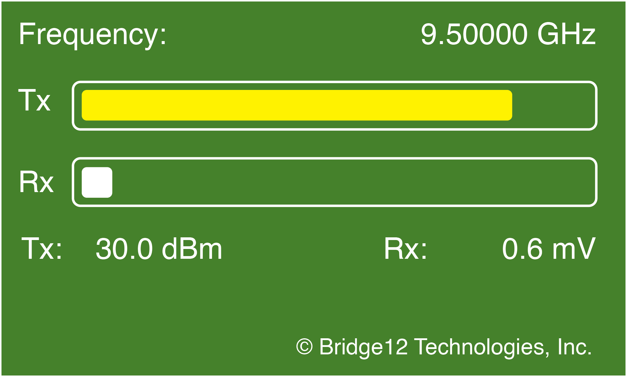
Figure 2.5 MPS Operate Screen
Note
If your system is not equipped with a detector for the forward power, the bar graph displays the set power. Only if a forward power monitor is installed, the actual forward power is displayed.
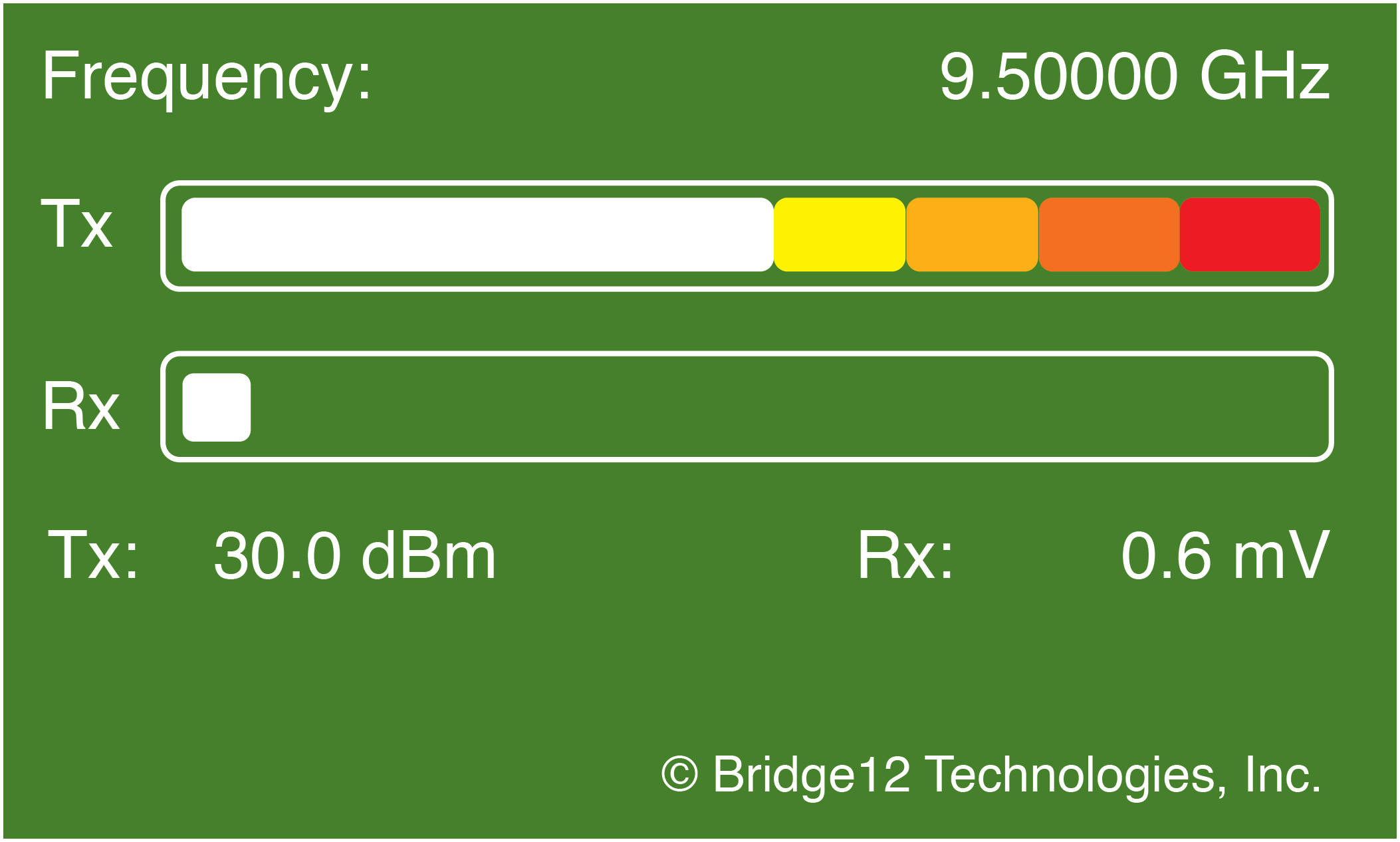
Figure 2.6 MPS Operate Screen, Color Code
Both, the Tx and Rx bar graph will change their color, depending on the amount of power. At low powers, the bar graph will be white. With increasing power the color will change from yellow, to orange at medium powers to red at high powers. This is indicated in Figure 2.6. The levels for the color to change are different for the Tx and Rx bar and are indicated in Table 2.1.
Color |
Tx [dBm] |
Rx [dBm] |
|---|---|---|
White |
0.0 - 23.0 |
0.0 - 15.0 |
Light Yellow |
> 23.0 - 28.0 |
> 15.0 - 18.0 |
Yellow |
> 28.0 - 31.0 |
> 18.0 - 21.0 |
Light Orange |
> 31.0 - 34.0 |
> 21.0 - 24.0 |
Orange |
> 34.0 - 37.0 |
> 24.0 - 27.0 |
Red |
> 37.0 |
> 27.0 |
One the center frequency of the resonator has been determined using the Sweep Screen the resonator can be fine tuned by moving the frequency and adjusting the resonator iris to minimize the reflected microwave power.
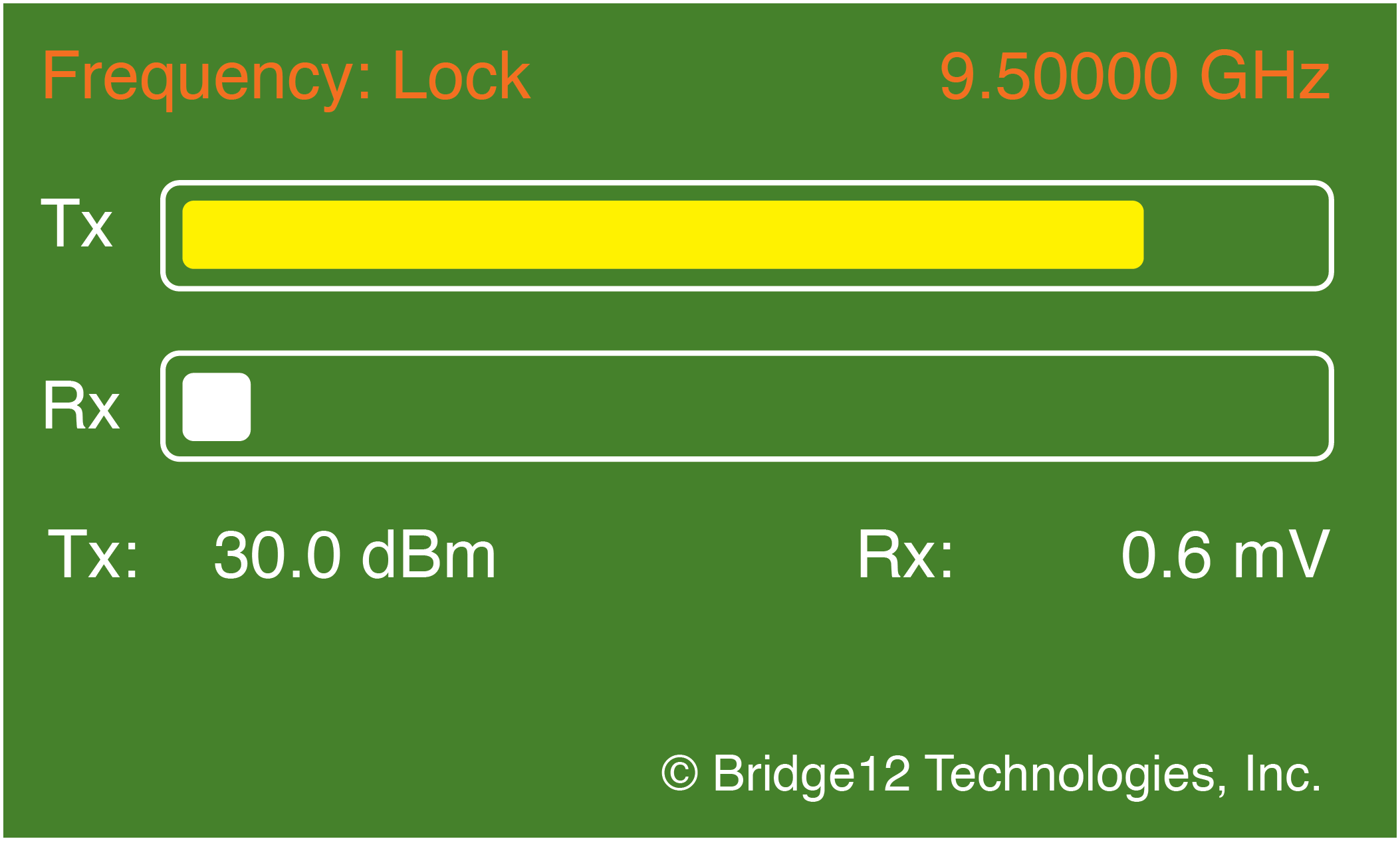
Figure 2.7 MPS Operate Screen and Frequency Lock enabled
2.1.4. Status Screen
The status screen can be accessed by pressing the rotary button for more than 2 seconds. To exit the status screen press the rotary button again.
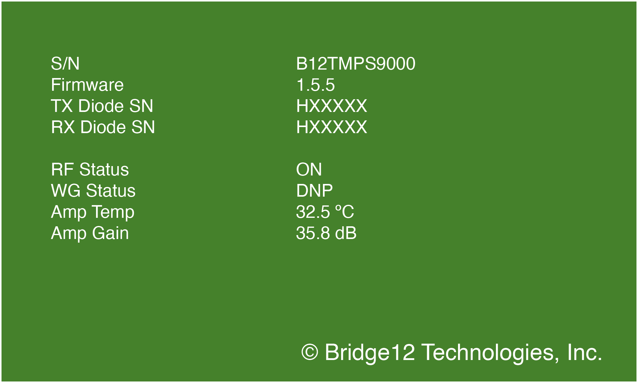
Figure 2.8 MPS Status Screen (the actual screen may vary depending on the firmware version)
The status screen provides additional system information, such as the amplifier temperature, the serial number and the current firmware version (see Figure 2.8).
2.2. Power Monitor (Rx and Tx)
The Bridge12 MPS has a built-in power monitoring circuit to constantly monitor the forward and reflected microwave power. An overview of the system is shown in Figure 2.9.
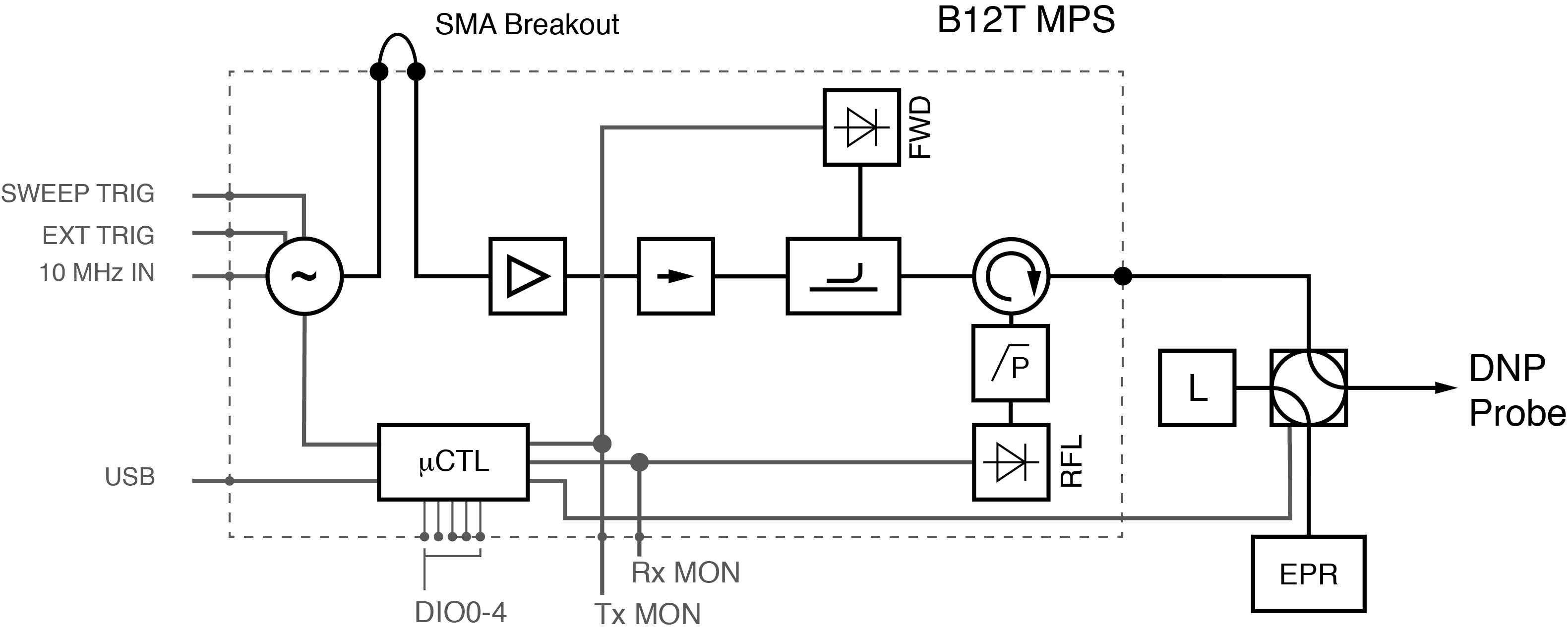
Figure 2.9 High-level schematics of the Bridge12 MPS
The forward and reflected power is detected using microwave detection diodes, which generate a voltage proportional to the measured microwave power. From this voltage, the integrated microcontroller calculates the microwave power. The microwave diodes are calibrated by Bridge12 at the time of delivery of the system. The calibration data is available upon request. Please contact Bridge12 at support@bridge12.com for further information.
The power monitor enables the following features:
Emergency Shutoff: If the reflected microwave power exceeds 33 dBm (2 W) the RF output power is automatically disabled. The user has to manually enable the RF output power to continue. Upon request, the default value can be changed.
Resonator Tuning: By sweeping the microwave frequency and monitoring the reflected power, the tuning dip of the resonator can be recorded.
Frequency Lock: Once the microwave power is increased, the resonator frequency can change due to thermal expansion of the resonator. The Frequency Lock will change the microwave frequency to minimize the reflected power, even when using the maximum output power.
These features are described in the Operation Section of this manual.